2.3.1.1 Placing the Camera
The POV-Ray camera has ten different models, each of which uses a different projection method to project the scene
onto your screen. Regardless of the projection type all cameras use the location, right, up,
direction, and keywords to determine the location and orientation of the camera. The type keywords and
these four vectors fully define the camera. All other camera modifiers adjust how the camera does its job. The meaning
of these vectors and other modifiers differ with the projection type used. A more detailed explanation of the camera
types follows later. In the sub-sections which follows, we explain how to place and orient the camera by the use of
these four vectors and the sky and look_at modifiers. You may wish to refer to the
illustration of the perspective camera below as you read about these vectors.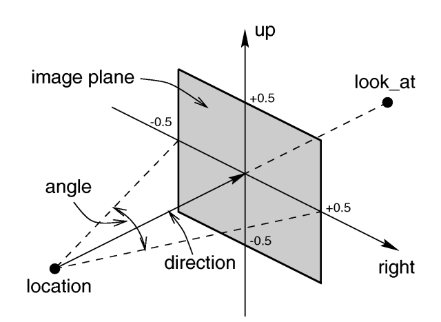
2.3.1.1.1 Location and Look_At
Under many circumstances just two vectors in the camera statement are all you need to position the camera: location
and look_at vectors. For example:
 camera {
  location <3,5,-10>
  look_at <0,2,1>
 }
The location is simply the x, y, z coordinates of the camera. The camera can be located anywhere in the ray-tracing
universe. The default location is <0,0,0>. The look_at vector tells POV-Ray to pan and
tilt the camera until it is looking at the specified x, y, z coordinates. By default the camera looks at a point one
unit in the z-direction from the location.
The look_at modifier should almost always be the last item in the camera statement. If other camera
items are placed after the look_at vector then the camera may not continue to look at the specified
point.
Normally POV-Ray pans left or right by rotating about the y-axis until it lines up with the look_at
point and then tilts straight up or down until the point is met exactly. However you may want to slant the camera
sideways like an airplane making a banked turn. You may change the tilt of the camera using the sky
vector. For example:
 camera {
  location <3,5,-10>
  sky   <1,1,0>
  look_at <0,2,1>
 }
This tells POV-Ray to roll the camera until the top of the camera is in line with the sky vector. Imagine that the
sky vector is an antenna pointing out of the top of the camera. Then it uses the sky vector as the axis
of rotation left or right and then to tilt up or down in line with the sky until pointing at the look_at
point. In effect you are telling POV-Ray to assume that the sky isn't straight up.
The sky vector does nothing on its own. It only modifies the way the look_at vector turns
the camera. The default value is sky<0,1,0>.
The angle keyword followed by a float expression specifies the (horizontal) viewing angle in degrees
of the camera used. Even though it is possible to use the direction vector to determine the viewing angle
for the perspective camera it is much easier to use the angle keyword.
When you specify the angle, POV-Ray adjusts the length of the direction vector
accordingly. The formula used is direction_length = 0.5 * right_length / tan(angle / 2) where
right_length is the length of the right vector. You should therefore specify the direction
and right vectors before the angle keyword. The right vector is explained in
the next section.
There is no limitation to the viewing angle except for the perspective projection. If you choose viewing angles
larger than 360 degrees you will see repeated images of the scene (the way the repetition takes place depends on the
camera). This might be useful for special effects.
The spherical camera has the option to also specify a vertical angle. If not specified it defaults to
the horizontal angle/2
For example if you render an image with a 2:1 aspect ratio and map it to a sphere using spherical mapping, it will
recreate the scene. Another use is to map it onto an object and if you specify transformations for the object before
the texture, say in an animation, it will look like reflections of the environment (sometimes called environment
mapping).
2.3.1.1.4 The Direction Vector
You will probably not need to explicitly specify or change the camera direction vector but it is
described here in case you do. It tells POV-Ray the initial direction to point the camera before moving it with the look_at
or rotate vectors (the default value is direction<0,0,1>). It may also be used to
control the (horizontal) field of view with some types of projection. The length of the vector determines the distance
of the viewing plane from the camera's location. A shorter direction vector gives a wider view while a
longer vector zooms in for close-ups. In early versions of POV-Ray, this was the only way to adjust field of view.
However zooming should now be done using the easier to use angle keyword.
If you are using the ultra_wide_angle, panoramic, or cylindrical projection
you should use a unit length direction vector to avoid strange results. The length of the
direction vector does not matter when using the orthographic, fisheye, or omnimax
projection types.
2.3.1.1.5 Up and Right Vectors
The primary purpose of the up and right vectors is to tell POV-Ray the relative height
and width of the view screen. The default values are:
 right 4/3*x
 up y
In the default perspective camera, these two vectors also define the initial plane of the view screen
before moving it with the look_at or rotate vectors. The length of the right
vector (together with the direction vector) may also be used to control the (horizontal) field of view
with some types of projection. The look_at modifier changes both the up and right
vectors. The angle calculation depends on the right vector.
Most camera types treat the up and right vectors the same as the perspective
type. However several make special use of them. In the orthographic projection: The lengths of the
up and right vectors set the size of the viewing window regardless of the direction
vector length, which is not used by the orthographic camera.
When using cylindrical projection: types 1 and 3, the axis of the cylinder lies along the up
vector and the width is determined by the length of right vector or it may be overridden with the angle
vector. In type 3 the up vector determines how many units high the image is. For example if you have up
4*y on a camera at the origin. Only points from y=2 to y=-2 are visible. All viewing rays are perpendicular to
the y-axis. For type 2 and 4, the cylinder lies along the right vector. Viewing rays for type 4 are
perpendicular to the right vector.
Note: that the up, right, and direction
vectors should always remain perpendicular to each other or the image will be distorted. If this is not the case a
warning message will be printed. The vista buffer will not work for non-perpendicular camera vectors.
Together the up and right vectors define the aspect ratio (height to width
ratio) of the resulting image. The default values up<0,1,0> and right<1.33,0,0>
result in an aspect ratio of 4 to 3. This is the aspect ratio of a typical computer monitor. If you wanted a tall
skinny image or a short wide panoramic image or a perfectly square image you should adjust the up and right
vectors to the appropriate proportions.
Most computer video modes and graphics printers use perfectly square pixels. For example Macintosh displays and IBM
SVGA modes 640x480, 800x600 and 1024x768 all use square pixels. When your intended viewing method uses square pixels
then the width and height you set with the Width and Height options or +W or +H
switches should also have the same ratio as the up and right vectors.
Note: 640/480 = 4/3 so the ratio is proper for this square pixel mode.
Not all display modes use square pixels however. For example IBM VGA mode 320x200 and Amiga 320x400 modes do not
use square pixels. These two modes still produce a 4/3 aspect ratio image. Therefore images intended to be viewed on
such hardware should still use 4/3 ratio on their up and right vectors but the pixel
settings will not be 4/3.
For example:
 camera {
  location <3,5,-10>
  up    <0,1,0>
  right  <1,0,0>
  look_at <0,2,1>
 }
This specifies a perfectly square image. On a square pixel display like SVGA you would use pixel settings such as +W480
+H480 or +W600 +H600. However on the non-square pixel Amiga 320x400 mode you would want to use
values of +W240 +H400 to render a square image.
The bottom line issue is this: the up and right vectors should specify the artist's
intended aspect ratio for the image and the pixel settings should be adjusted to that same ratio for square pixels and
to an adjusted pixel resolution for non-square pixels. The up and right vectors should
not be adjusted based on non-square pixels.
The right vector also describes the direction to the right of the camera. It tells POV-Ray where the
right side of your screen is. The sign of the right vector can be used to determine the handedness of the
coordinate system in use. The default value is: right<1.33,0,0>. This means that the +x-direction
is to the right. It is called a left-handed system because you can use your left hand to keep track of the
axes. Hold out your left hand with your palm facing to your right. Stick your thumb up. Point straight ahead with your
index finger. Point your other fingers to the right. Your bent fingers are pointing to the +x-direction. Your thumb
now points into +y-direction. Your index finger points into the +z-direction.
To use a right-handed coordinate system, as is popular in some CAD programs and other ray-tracers, make the same
shape using your right hand. Your thumb still points up in the +y-direction and your index finger still points forward
in the +z-direction but your other fingers now say the +x-direction is to the left. That means that the right side of
your screen is now in the -x-direction. To tell POV-Ray to act like this you can use a negative x value in the
right vector such as: right<-1.33,0,0>. Since having x values increasing to the left does
not make much sense on a 2D screen you now rotate the whole thing 180 degrees around by using a positive z value in
your camera's location. You end up with something like this.
 camera {
  location <0,0,10>
  up    <0,1,0>
  right  <-1.33,0,0>
  look_at <0,0,0>
 }
Now when you do your ray-tracer's aerobics, as explained in the section "Understanding
POV-Ray's Coordinate System", you use your right hand to determine the direction of rotations.
In a two dimensional grid, x is always to the right and y is up. The two versions of handedness arise from the
question of whether z points into the screen or out of it and which axis in your computer model relates to up in the
real world.
Architectural CAD systems, like AutoCAD, tend to use the God's Eye orientation that the z-axis is the
elevation and is the model's up direction. This approach makes sense if you are an architect looking at a building
blueprint on a computer screen. z means up, and it increases towards you, with x and y still across and up the screen.
This is the basic right handed system.
Stand alone rendering systems, like POV-Ray, tend to consider you as a participant. You are looking at the screen
as if you were a photographer standing in the scene. The up direction in the model is now y, the same as up in the
real world and x is still to the right, so z must be depth, which increases away from you into the screen. This is the
basic left handed system.
2.3.1.1.8 Transforming the Camera
The various transformations such as translate and rotate modifiers can re-position the
camera once you have defined it. For example:
 camera {
  location < 0, 0, 0>
  direction < 0, 0, 1>
  up    < 0, 1, 0>
  right   < 1, 0, 0>
  rotate  <30, 60, 30>
  translate < 5, 3, 4>
 }
In this example, the camera is created, then rotated by 30 degrees about the x-axis, 60 degrees about the y-axis
and 30 degrees about the z-axis, then translated to another point in space.
|


