|
 |
1.3.10.2 The idea and the code
The idea is to raytrace a simple scene consisting of spheres and light sources into a 2-dimensional array
containing color vectors which represents our "screen".
After this we just have to put those colors on the actual scene for POV-Ray to show them. This is made by creating
a flat colored triangle mesh. The mesh is just flat like a plane with a color map on it. We could as well have written
the result to a format like PPM and then read it and apply it as an image map to a plane, but this way we avoid a
temporary file.
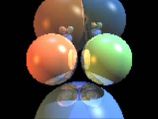
The following image is done with the raytracer SDL. It calculated the image at a resolution of 160x120 pixels and
then raytraced an 512x384 image from it. This causes the image to be blurred and jagged (because it is practically
"zoomed in" by a factor of 3.2). Calculating the image at 320x240 gives a much nicer result, but it is also
much slower:

Note: there are no real spheres nor light sources here ("real" from the
point of view of POV-Ray), just a flat colored triangle mesh (like a plane with a pigment on it) and a camera, nothing
else.
Here is the source code of the raytracer; we will look it part by part through this tutorial.
#declare ImageWidth = 160;
#declare ImageHeight = 120;
#declare MaxRecLev = 5;
#declare AmbientLight = <.2,.2,.2>;
#declare BGColor = <0,0,0>;

// Sphere information.
// Values are:
// Center, <Radius, Reflection, 0>, Color, <phong_size, amount, 0>
#declare Coord = array[5][4]
{ {<-1.05,0,4>, <1,.5,0>, <1,.5,.25>, <40, .8, 0>}
  {<1.05,0,4>, <1,.5,0>, <.5,1,.5>, <40, .8, 0>}
  {<0,-3,5>, <2,.5,0>, <.25,.5,1>, <30, .4, 0>}
  {<-1,2.3,9>, <2,.5,0>, <.5,.3,.1>, <30, .4, 0>}
  {<1.3,2.6,9>, <1.8,.5,0>, <.1,.3,.5>, <30, .4, 0>}
}

// Light source directions and colors:
#declare LVect = array[3][2]
{ {<-1, 0, -.5>, <.8,.4,.1>}
  {<1, 1, -.5>, <1,1,1>}
  {<0,1,0>, <.1,.2,.5>}
}


//==================================================================
// Raytracing calculations:
//==================================================================
#declare MaxDist = 1e5;
#declare ObjAmnt = dimension_size(Coord, 1);
#declare LightAmnt = dimension_size(LVect, 1);

#declare Ind = 0;
#while(Ind < LightAmnt)
  #declare LVect[Ind][0] = vnormalize(LVect[Ind][0]);
  #declare Ind = Ind+1;
#end

#macro calcRaySphereIntersection(P, D, sphereInd)
  #local V = P-Coord[sphereInd][0];
  #local R = Coord[sphereInd][1].x;

  #local DV = vdot(D, V);
  #local D2 = vdot(D, D);
  #local SQ = DV*DV-D2*(vdot(V, V)-R*R);
  #if(SQ < 0) #local Result = -1;
  #else
    #local SQ = sqrt(SQ);
    #local T1 = (-DV+SQ)/D2;
    #local T2 = (-DV-SQ)/D2;
    #local Result = (T1<T2 ? T1 : T2);
  #end
  Result
#end

#macro Trace(P, D, recLev)
  #local minT = MaxDist;
  #local closest = ObjAmnt;

  // Find closest intersection:
  #local Ind = 0;
  #while(Ind < ObjAmnt)
    #local T = calcRaySphereIntersection(P, D, Ind);
    #if(T>0 & T<minT)
      #local minT = T;
      #local closest = Ind;
    #end
    #local Ind = Ind+1;
  #end

  // If not found, return background color:
  #if(closest = ObjAmnt)
    #local Pixel = BGColor;
  #else
    // Else calculate the color of the intersection point:
    #local IP = P+minT*D;
    #local R = Coord[closest][1].x;
    #local Normal = (IP-Coord[closest][0])/R;

    #local V = P-IP;
    #local Refl = 2*Normal*(vdot(Normal, V)) - V;

    // Lighting:
    #local Pixel = AmbientLight;
    #local Ind = 0;
    #while(Ind < LightAmnt)
      #local L = LVect[Ind][0];

      // Shadowtest:
      #local Shadowed = false;
      #local Ind2 = 0;
      #while(Ind2 < ObjAmnt)
        #if(Ind2!=closest & calcRaySphereIntersection(IP,L,Ind2)>0)
          #local Shadowed = true;
          #local Ind2 = ObjAmnt;
        #end
        #local Ind2 = Ind2+1;
      #end

      #if(!Shadowed)
        // Diffuse:
        #local Factor = vdot(Normal, L);
        #if(Factor > 0)
          #local Pixel=Pixel+LVect[Ind][1]*Coord[closest][2]*Factor;
        #end

        // Specular:
        #local Factor = vdot(vnormalize(Refl), L);
        #if(Factor > 0)
          #local Pixel =
             Pixel +
             LVect[Ind][1]*pow(Factor, Coord[closest][3].x)*
             Coord[closest][3].y;
        #end
      #end
      #local Ind = Ind+1;
    #end

    // Reflection:
    #if(recLev < MaxRecLev & Coord[closest][1].y > 0)
      #local Pixel =
	    Pixel + Trace(IP, Refl, recLev+1)*Coord[closest][1].y;
    #end
  #end

  Pixel
#end


#debug "Rendering...\n\n"
#declare Image = array[ImageWidth][ImageHeight]
#declare IndY = 0;
#while(IndY < ImageHeight)
  #declare CoordY = IndY/(ImageHeight-1)*2-1;
  #declare IndX = 0;
  #while(IndX < ImageWidth)
    #declare CoordX =
      (IndX/(ImageWidth-1)-.5)*2*ImageWidth/ImageHeight;
    #declare Image[IndX][IndY] =
      Trace(-z*3, <CoordX, CoordY, 3>, 1);
    #declare IndX = IndX+1;
  #end
  #declare IndY = IndY+1;
  #debug concat("\rDone ", str(100*IndY/ImageHeight, 0, 1),
    "%  (line ",str(IndY,0,0)," out of ",str(ImageHeight,0,0),")")
#end
#debug "\n"


//==================================================================
// Image creation (colored mesh):
//==================================================================
#default { finish { ambient 1 } }

#debug "Creating colored mesh to show image...\n"
mesh2
{ vertex_vectors
  { ImageWidth*ImageHeight*2,
    #declare IndY = 0;
    #while(IndY < ImageHeight)
      #declare IndX = 0;
      #while(IndX < ImageWidth)
        <(IndX/(ImageWidth-1)-.5)*ImageWidth/ImageHeight*2,
         IndY/(ImageHeight-1)*2-1, 0>,
        <((IndX+.5)/(ImageWidth-1)-.5)*ImageWidth/ImageHeight*2,
         (IndY+.5)/(ImageHeight-1)*2-1, 0>
        #declare IndX = IndX+1;
      #end
      #declare IndY = IndY+1;
    #end
  }
  texture_list
  { ImageWidth*ImageHeight*2,
    #declare IndY = 0;
    #while(IndY < ImageHeight)
      #declare IndX = 0;
      #while(IndX < ImageWidth)
        texture { pigment { rgb Image[IndX][IndY] } }
        #if(IndX < ImageWidth-1 & IndY < ImageHeight-1)
          texture { pigment { rgb
            (Image[IndX][IndY]+Image[IndX+1][IndY]+
             Image[IndX][IndY+1]+Image[IndX+1][IndY+1])/4 } }
        #else
          texture { pigment { rgb 0 } }
        #end
        #declare IndX = IndX+1;
      #end
      #declare IndY = IndY+1;
    #end
  }
  face_indices
  { (ImageWidth-1)*(ImageHeight-1)*4,
    #declare IndY = 0;
    #while(IndY < ImageHeight-1)
      #declare IndX = 0;
      #while(IndX < ImageWidth-1)
        <IndX*2+  IndY    *(ImageWidth*2),
         IndX*2+2+IndY    *(ImageWidth*2),
         IndX*2+1+IndY    *(ImageWidth*2)>,
         IndX*2+  IndY    *(ImageWidth*2),
         IndX*2+2+IndY    *(ImageWidth*2),
         IndX*2+1+IndY    *(ImageWidth*2),

        <IndX*2+  IndY    *(ImageWidth*2),
         IndX*2+  (IndY+1)*(ImageWidth*2),
         IndX*2+1+IndY    *(ImageWidth*2)>,
         IndX*2+  IndY    *(ImageWidth*2),
         IndX*2+  (IndY+1)*(ImageWidth*2),
         IndX*2+1+IndY    *(ImageWidth*2),

        <IndX*2+  (IndY+1)*(ImageWidth*2),
         IndX*2+2+(IndY+1)*(ImageWidth*2),
         IndX*2+1+IndY    *(ImageWidth*2)>,
         IndX*2+  (IndY+1)*(ImageWidth*2),
         IndX*2+2+(IndY+1)*(ImageWidth*2),
         IndX*2+1+IndY    *(ImageWidth*2),

        <IndX*2+2+IndY    *(ImageWidth*2),
         IndX*2+2+(IndY+1)*(ImageWidth*2),
         IndX*2+1+IndY    *(ImageWidth*2)>,
         IndX*2+2+IndY    *(ImageWidth*2),
         IndX*2+2+(IndY+1)*(ImageWidth*2),
         IndX*2+1+IndY    *(ImageWidth*2)
        #declare IndX = IndX+1;
      #end
      #declare IndY = IndY+1;
    #end
  }
}

camera { orthographic location -z*2 look_at 0 }
|
 |


